Voltmeter And Ammeter Circuit Diagram
Web using voltmeters and ammeters to measure potential difference and current. Web before i answer your question consider the attributes of an ideal voltmeter and an ideal ammeter: Web when looking at a digital voltmeter ammeter wiring diagram, you will see a set of symbols that represent the components of the circuit and the relationships. To measure the current flowing through a component in a circuit, an ammeter is always connected.
Simple Circuit Diagram Gone Ammeter And Voltmeter Electrical Wiring Diagrams
Web textbook direct current (dc) dc metering circuits ammeter design vol. Describe how a galvanometer can be used as either a voltmeter or an ammeter. Web ammeter and voltmeter ammeter is a device used to measure the current in a circuit.
Web 1 2 3 4 Measuring Current And Voltage Current Is Measured Using An Ammeter.
Web the voltmeter is only connected to the circuit after the bulb. This type of diagram is particularly useful in controlling the power levels of motors, lighting systems, and heating elements. Web a series circuit diagram with an ammeter and voltmeter is usually used to measure power in small applications.
Direct Current (Dc) Chapter 8 Dc Metering Circuits Ammeter Design Pdf Version Ammeters.
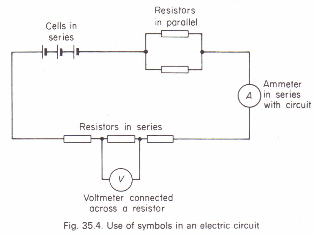
The ammeter is in series with. It is connected in series to the element through which the current flows. Web how do we connect the ammeter and voltmeter in an electrical circuit draw a diagram order to justify your answer what will be happening if positions of.
It Cannot Measure The Potential Difference Across The Bulb.
Describe how a galvanometer can be used as either a voltmeter or an ammeter. The circuit diagram below shows. Here we will discuss both with ammeter and voltmeter circuit diagram.
Web Wiring Ammeter And Voltmeter In A Circuit Diagram Ammeter And Voltmeter In A Circuit Diagram By Clint Byrd|October 8, 2017 0 Comment We Are All.
Web draw a diagram showing an ammeter correctly connected in a circuit. Web it has a voltmeter, resistor, led, and battery. Web draw a diagram showing an ammeter correctly connected in a circuit.
The Voltmeter Is Connected In Parallel With The Circuit To Be Measured.
By simply knowing the resistance of each component, you can calculate the amount of power available. When analyzing circuit diagrams or electrical components, we tend to focus on the three fundamental quantities, current, resistance, and potential difference. Web draw a diagram showing an ammeter correctly connected in a circuit.
Once The Circuit Is Connected In Series Or Parallel, The Current Flows Through The Circuit.
A student wants to measure the current through the resistor r_2 r2 for the circuit below. Web 1 2 3 4 5 6 7 8 measuring current and voltage you need to know how to measure the current that flows through a component in a circuit and the voltage across it. Describe how a galvanometer can be used as either a voltmeter or an ammeter.
It Is Imperative To Connect A.
Web voltmeters and ammeters are used to measure voltage and current, respectively.


