Lr Circuit Phasor Diagram
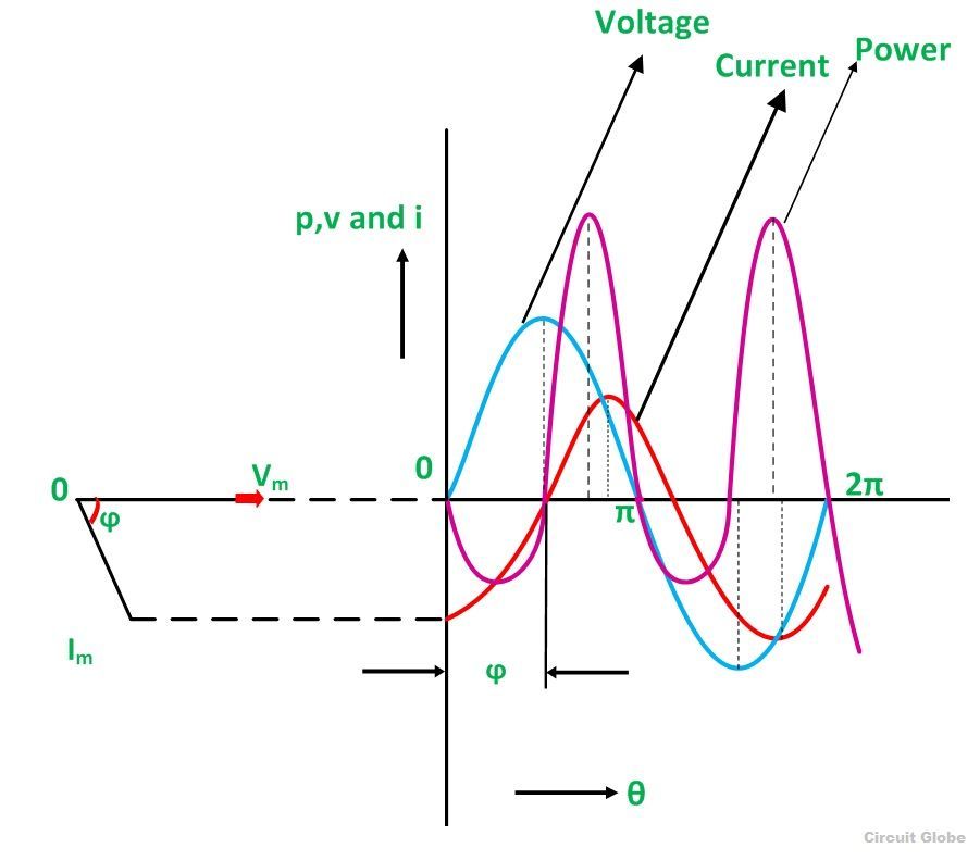
4) impedance triangle of series rl circuit. Web a lr series circuit consists basically of an inductor of inductance, l connected in series with a resistor of resistance, r. Fig 10.1.2 shows phasor diagrams for the circuit in fig 10.1.1 under three different conditions, below, above and at resonance. Change how the circuit is driven by adjusting.
Phasor Diagram For Lrc Circuit Youtube
Web phasor diagrams 🔥 purely resistive, capacitive & inductive ac circuit ⭐ lr circuit #accircuits phasor diagrams,phasor diagram,phasor diagram ac. The resistance “r” is the dc resistive value of the wire. Copy to clipboard source fullscreen this demonstration shows a phasor diagram in.
Frequency F Of The Applied Signal In Relation To The Frequency Of Resonance F0.
This simulation shows the phasor representation of a series rlc circuit. Web the phasor diagram for a parallel rlc circuit is produced by combining together the three individual phasors for each component and adding the currents vectorially. Adjust the values of r, l, and c using the sliders.
Web Phasor Diagram For Series Rlc Circuits Download To Desktop Copying.
Unlike the phasor diagrams for. 5) power triangle of series rl circuit. Three different cases may be considered:
The Nature Of The Phasor Diagram Of A Series Rlc Circuit Depends On The.
(i) f = fr, (ii) f. Web an example of series rlc circuit and respective phasor diagram for a specific ω.the arrows in the upper diagram are phasors, drawn in a phasor diagram (complex plane without axis shown), which must not be confused with the arrows in the lower diagram, which are the reference polarity for the voltages and the reference direction for the. 3) voltage triangle of series rl circuit.
Phasor Diagrams Are Used In Electrical Engineering To Represent The Relationship Of Different Ac Signals At An Instant Of Time.
Web 2) phasor diagram of series rl circuit. Web 12.3 phasor diagram of series rlc circuit.


